Silicon Drift Detectors (SDD) Principle of Operation
The Sensor
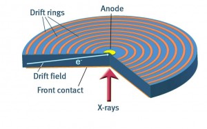
Silicon Drift Detectors SDD are essentially 450μm thick discs of high-resistivity Silicon which is fully depleted by applying a negative bias voltage to both sides of the disc. On one side of the planar structure the bias is graduated across the device by means of a series of ‘drift rings’ such that a strong transverse electric field component is developed within the structure. This is used to direct electrons produced as a result of x-ray interactions towards a small charge collecting anode. On the opposite side of the device (x-ray entrance side) there is a uniform shallow implanted junction contact to allow good low energy x-ray sensitivity and minimum charge loss. This drift detector structure has very low capacitance which provides excellent energy resolution at relatively short electronic processing times and also allows operation at very high count rates. Additionally, Silicon Drift Detectors have very low leakage current so optimum performance can be achieved at temperatures which are readily reached by electronic Peltier cooling systems, removing the need for liquid Nitrogen.
The Preamplifier
The preamplifier consists of a low noise charge sensitive amplifier in conjunction with an input FET (field effect transistor) which is localised at the sensor. When signal electrons are collected at the anode via the drift field in the sensor they are transferred to the gate of the FET. The preamplifier integrates this signal charge Qs into a voltage step Vstep via a feedback capacitor Cf. The size of the voltage step is

This voltage step is then further amplified in order to meet the input requirements of the Pulse Processor.
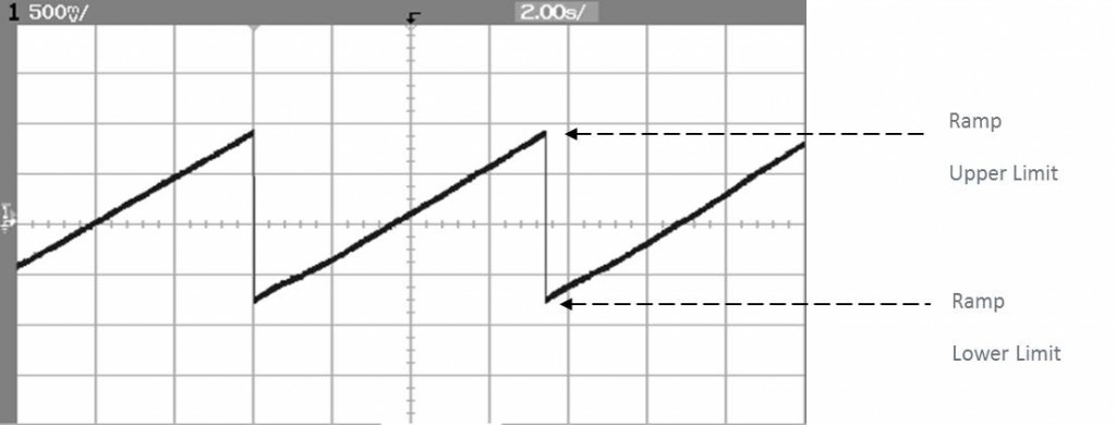
With no x-rays present the signal charge is due only to thermally generated electrons. This is called the leakage current of the sensor. The leakage current increasingly charges the integrating capacitor such that a voltage ‘ramp’ is observed at the preamplifier output. This continues until an upper level or limit is reached whereupon a ‘reset’ pulse of opposite polarity is used to neutralise the accumulated charge. This produces a typical preamplifier output signal as shown below.